Posted by Ondrej M on 26th Feb 2025
Building the dream - Part 5 Engine and drive train
Engine installation with the drivetrain: My Year-Long DIY Honda S2000 Restoration Journey
Installing the engine will be fun—well, this is meant with a healthy dose of sarcasm. I knew I didn’t want to be hoisting the engine in from the top and then reconnecting the gearbox, so I came up with a new plan: place the engine on the front subframe, attach the earbox, and slide the entire assembly in from the bottom. This meant I had to lift the shell that little bit more.
Before I could attach the gearbox, it was time to install the clutch.
First things first—installing the new flywheel. Although the previous flywheel had only covered less than 20k miles, I opted for a new one. After all, this is a job I don’t want to do again for a very, very long time.
Proper alignment was crucial. I torqued the new flywheel bolts according to the Honda workshop manual, which also recommends not reusing the old bolts.
I modified a 17mm, 12-sided socket to sit flush with the base of the bolt. This provided maximum grip and prevented the bolt head from rounding off.
Actually, I modified that 17mm socket much earlier, as I needed it to remove the old flywheel. That had to be done because I was also replacing the crank seal.
Before I was ready to install the clutch and join the gearbox with the engine, I wanted to ensure the flywheel sat perfectly in place. To verify this, I used a spring-loaded gauge, mounting one end to the crankcase and the other to inspect for any deviations in measurement while manually turning the crankshaft.
I didn’t really document the clutch replacement—it’s a shame. However, if you’ve ever watched the "LHT Performance" channel on YouTube, they provide some great tips and detailed videos on what to do, what not to do, and which parts are recommended for replacement, even if the manual doesn’t mention them.
For the list of parts, I started with an original Honda clutch kit and original Honda release bearing. I also replaced the clutch release bearing guide, input shaft seal in the gearbox, clutch release fork, clutch slave cylinder, and the rubber cover for the clutch slave cylinder.
Special care was taken when applying Honda Urea grease.
And if you're wondering what happened to the new cover—well, as I worked around the engine, lifting it with a crane and sliding it under the car, I decided to put the old one on for now. 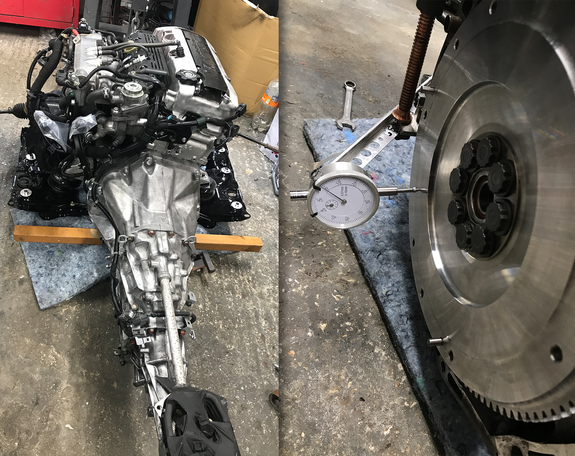
Before the engine was lifted into place, I also added rigid collars to the subframe from Delta Lima Engineering, a company based in the Netherlands. While I have plenty of Spoon parts on this car, the rigid collars from Delta Lima were much more affordable. Additionally, I didn’t want to risk buying low-grade fakes at full price on eBay.
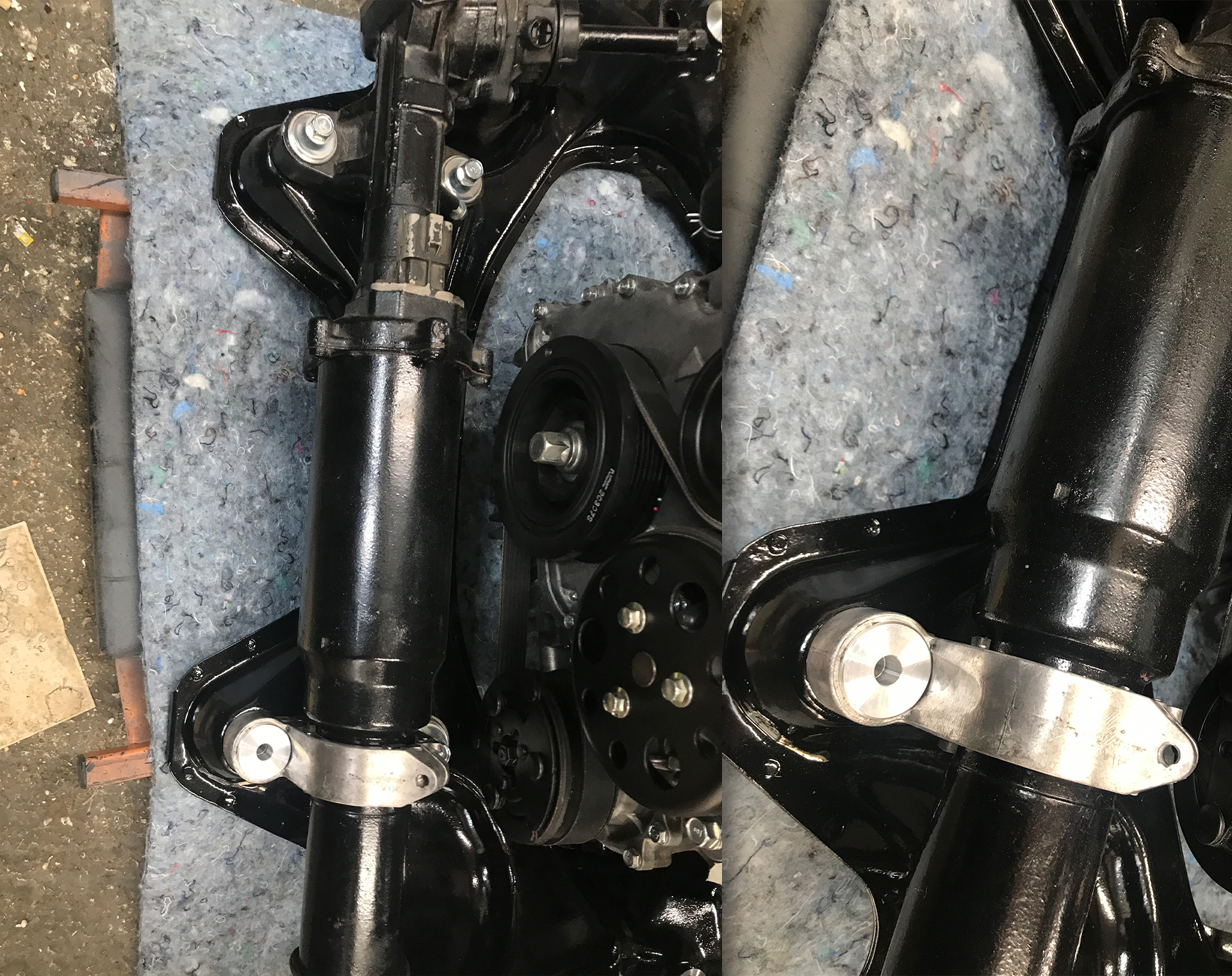
As mentioned earlier, I found that lifting the car shell a bit higher and sliding the engine underneath was much safer and easier. Although the poor car creeper somehow managed to withstand the full weight of the engine and gearbox, it was borderline sketchy. But hey, this is DIY, is it not?
As one wise man once said (Bear Grylls)
Improvise, Adapt, Overcome!
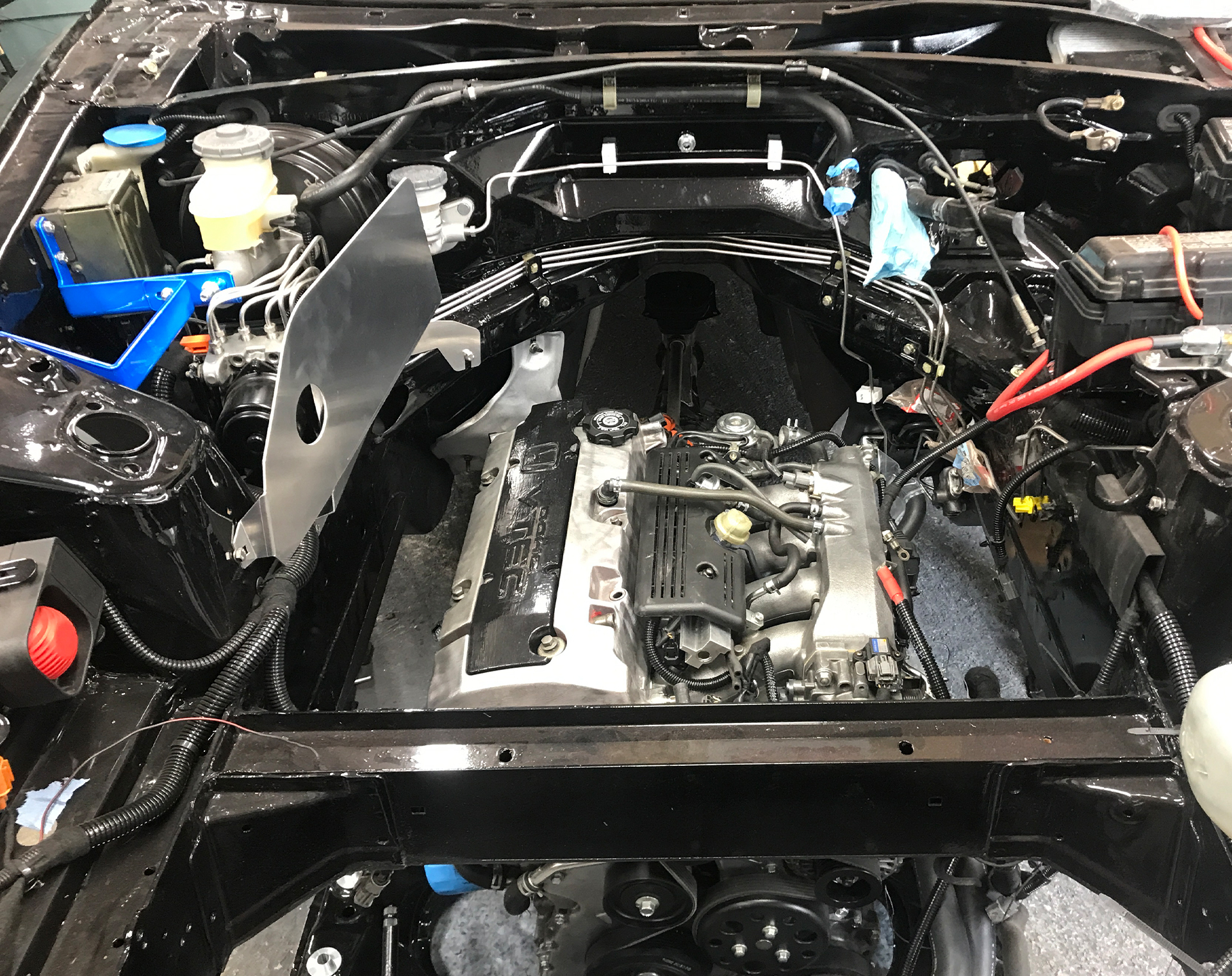
Once the engine was in place, I used an engine crane to very slowly and carefully lift it until I was able to secure the subframe with a set of new bolts. Although I had restored the old set, I later changed my mind and decided to get new ones. Besides, the Honda manual recommends using a new set anyway.
Getting the subframe positioned correctly and leveled is more critical than it seems. The main reason is that if the subframe bolts are not threaded in perfectly, they can damage the threads in the chassis, leading to a cross-threading nightmare— and fixing that is a whole new level of hell.
I started by carefully locating the threads and threading the bolts in by hand with a bit of anti-seize, ensuring they were fully engaged and going in smoothly. Once I could no longer tighten them by hand, I switched to a smaller ratchet, making sure each turn had no resistance. At no point did I use electric or pneumatic tools to tighten these bolts.
Not only is it important to keep the bolts straight, but it’s also crucial to tighten them in a cross pattern while checking the frame alignment as it is slowly raised toward the car body. This is where the rigid collars help. The subframe has oversized holes for easier installation at the factory, and the main purpose of the collars is to fill those gaps between the subframe and the car body, reducing movement during cornering—at least in theory.
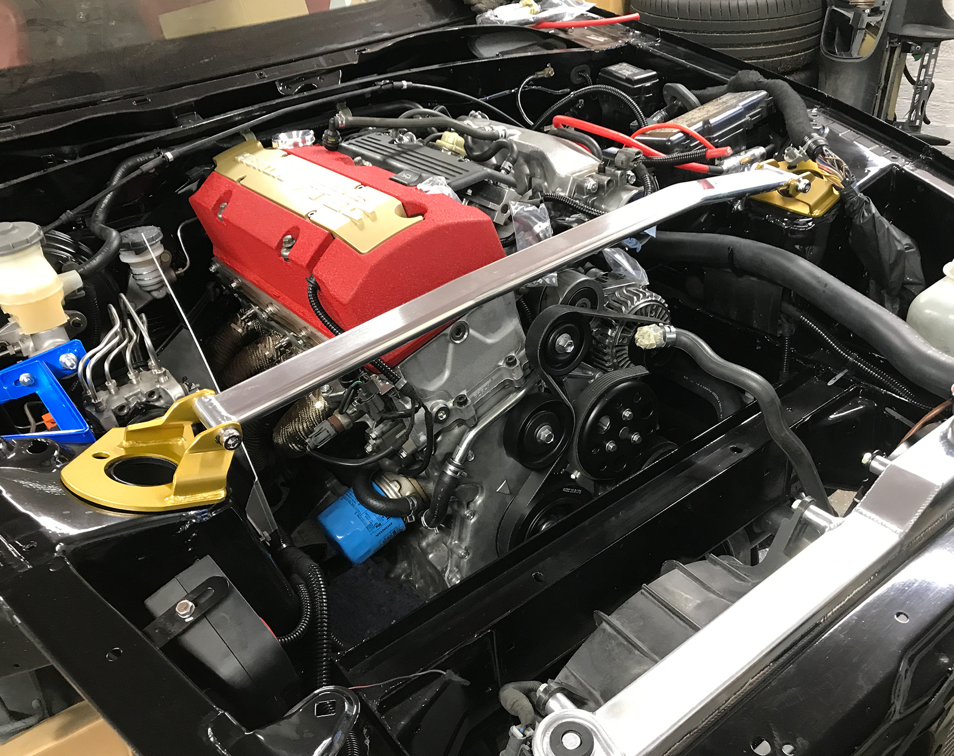
Before lifting the engine, I also attached the exhaust manifold. Instead of using the original studs and nuts, I switched to titanium ones because I didn’t like how the original ones would look after a couple of years. Yes, many of my replacements and upgrades are purely for cosmetic reasons rather than performance or handling improvements.
Just above the exhaust manifold is the JS Racing heat shield, which has a cutout for the engine torque damper.
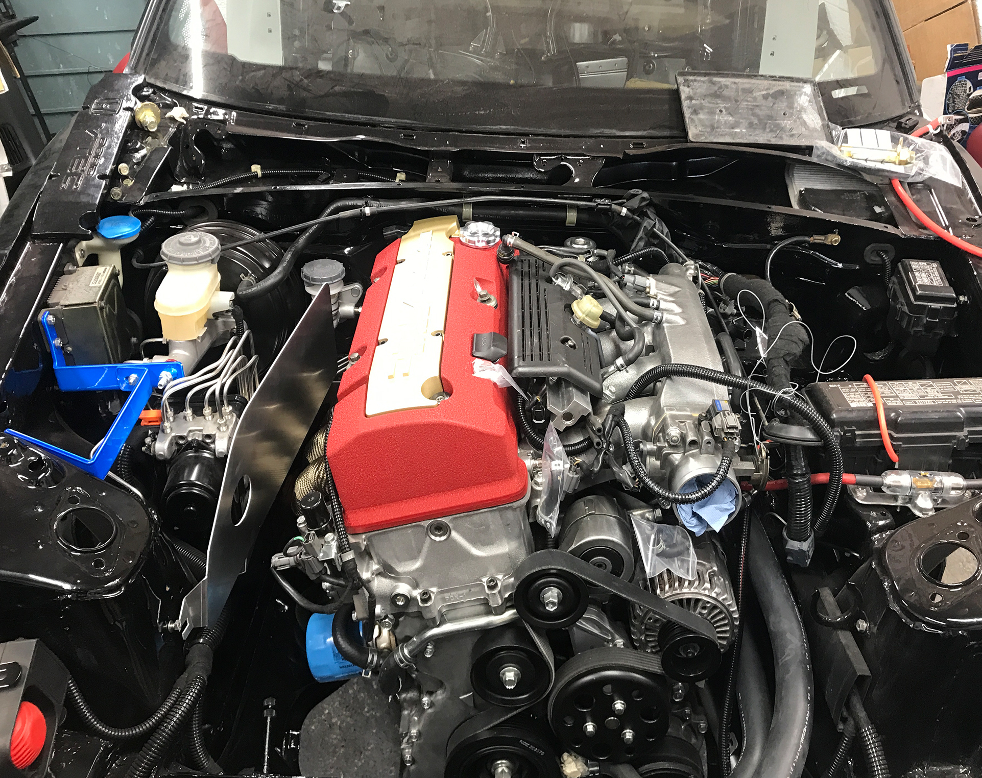
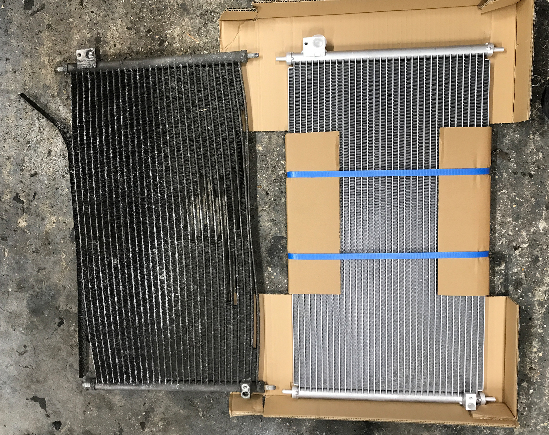
Replacing the original AC condenser, as the old one was in a bit of a sorry state. It was still functional; however, it was already missing a lot of fins, and the ones that remained were neither particularly straight nor optimal for airflow.
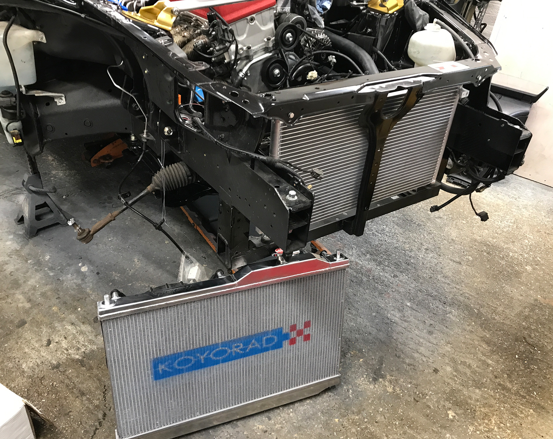
Also not making a return was the original radiator—instead, I went with a Koyorad. This radiator purchase also led to some unexpected additional purchases.
When I bought the radiator, I also ordered the matching Koyorad radiator cap. However, when the radiator arrived, the cap was missing. These things happen, so I called the company I ordered from. The lady on the phone apologized for the mishap and immediately offered to send the cap. She must have had some kind of spider sense because, out of nowhere, she mentioned a JS Racing strut bar brace at a discounted price. The offer was too good to refuse, so yeah… more money gone.
That said, I have to admit, the strut bar looks great. It adds a nice shine to the engine bay, and the gold ends perfectly match the Öhlins suspension—but more on those in the next chapter.
I don’t mind when a company makes mistakes; these things happen. What truly separates good companies from bad ones is how they handle issues when they arise. And I have to say, throughout this build, I’ve encountered a few hiccups with my orders, but every company I’ve dealt with has had exceptional customer service.
Unfortunately, I wasn’t able to find a JS Racing engine torque damper. Luckily, though, Tegiwa offers their own version, which appears to be made to match the JS Racing fixings.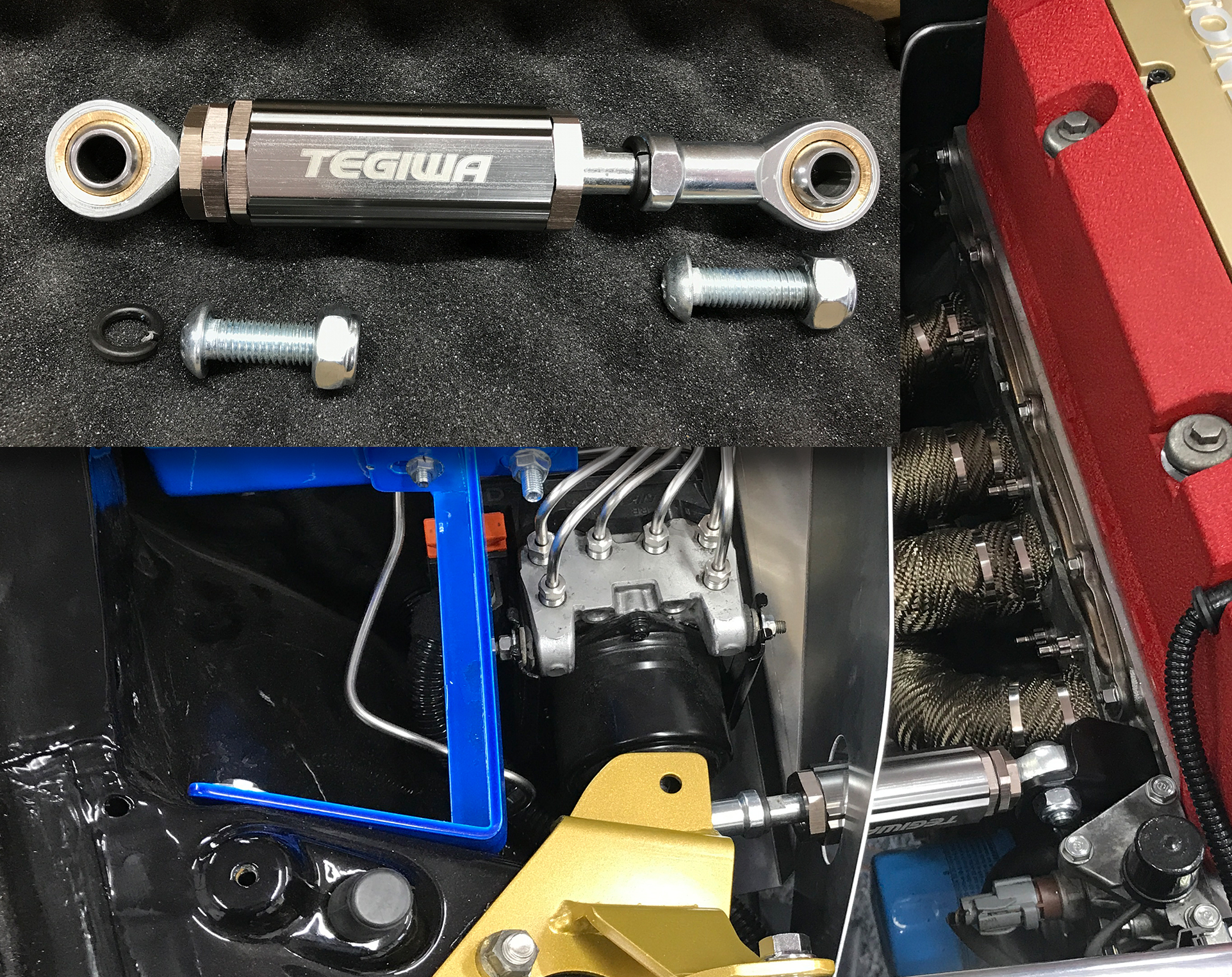
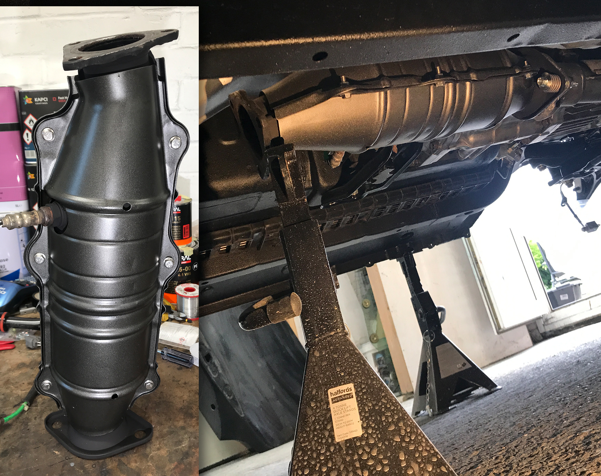
To complete the engine installation, I reconnected all hoses and wiring, connected the engine loom back to the ECU, and reattached it to the fuse box and battery terminal. On the exhaust side, I gave the catalytic converter and its cover a fresh coat of UHT paint.
However, I made a fatal mistake—one that I would only discover later. Instead of connecting the O₂ sensors to the ECU, I somehow managed to connect the ECU to itself, which ended up burning out one of the transistors inside.
Luckily, when I visited TGM in Fleet, Tom had a few ECUs in stock. He kindly offered to let me borrow one so I could check the component part number and order the transistor from an electronics supplier like Farnell or RS. In the end, I decided to just buy it from him instead. I would have needed to open the ECU, and if he later sold it to someone and it didn’t work, I wouldn’t want him to be suspicious of me.
Differential Rebuild & Upgrade
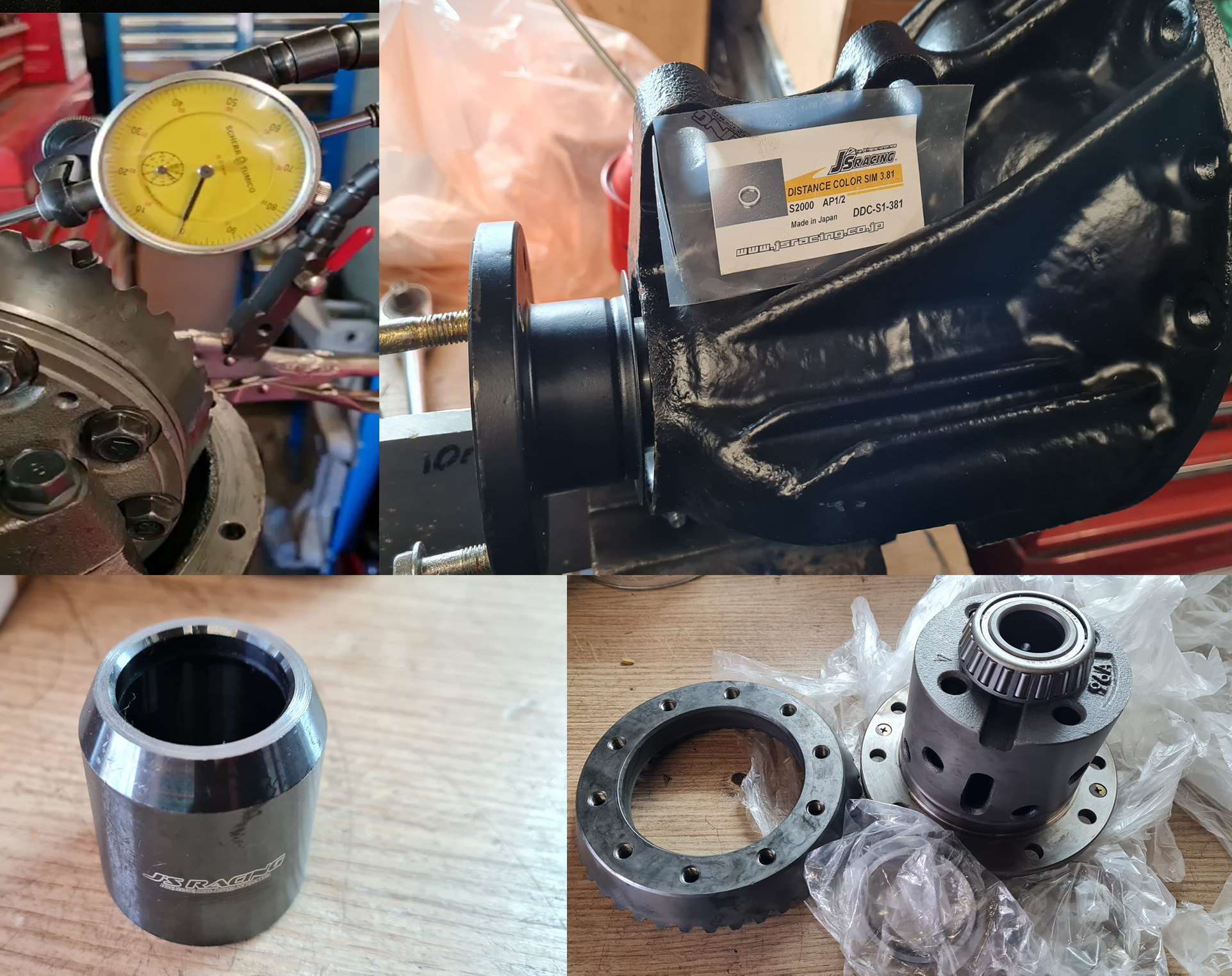
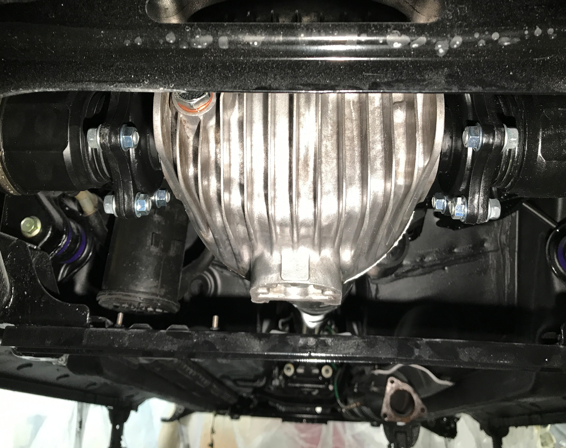
With the engine now in place, let's focus on the rest of the drivetrain. I’ve watched many YouTube videos on differential rebuilds, and one channel really stood out—PuddyModRacing. His videos provide an in-depth look at the rebuild process and how to fix the inherent weakness of the crush pinion nut, which is supposed to maintain proper backlash in the differential gears.
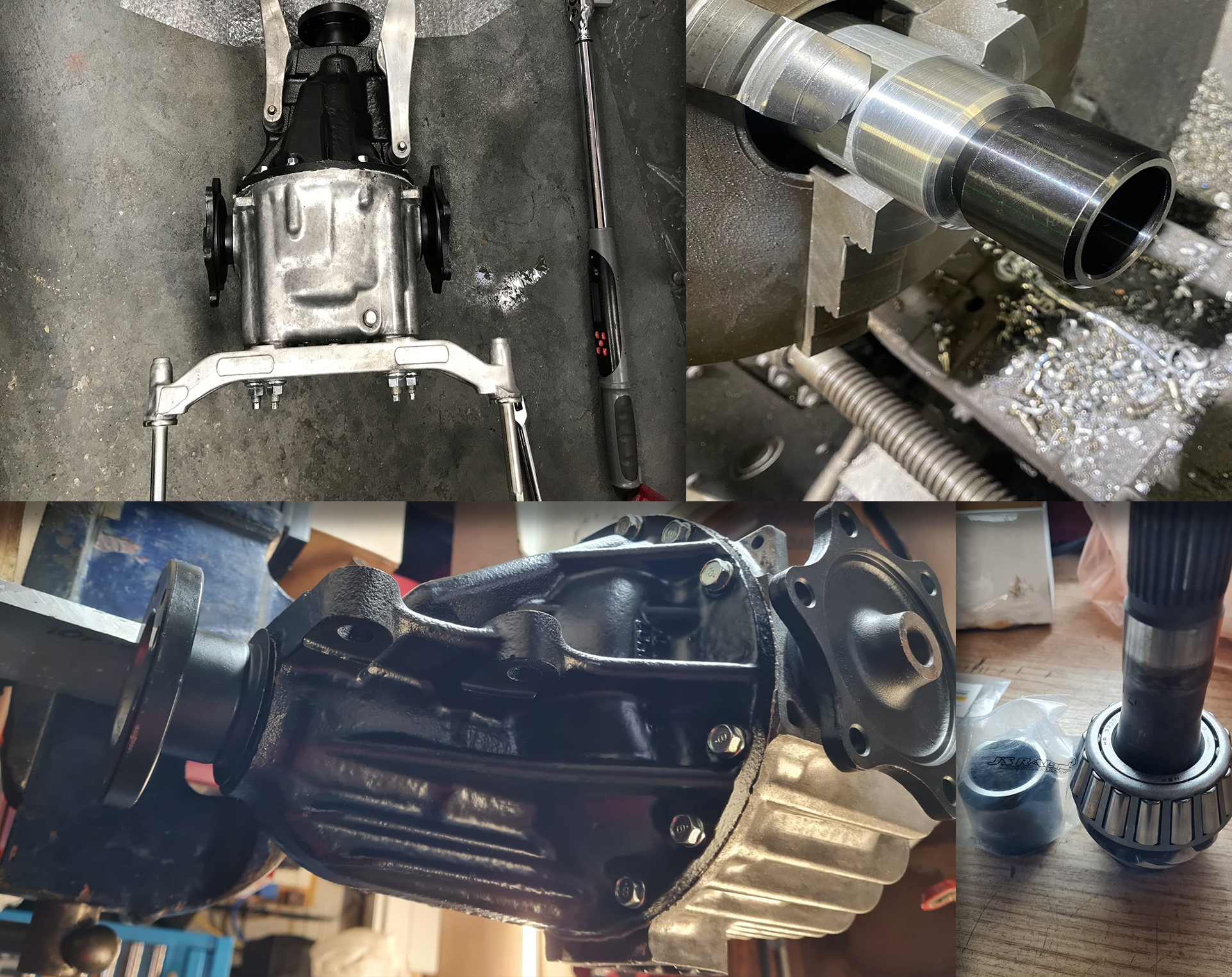
I began by taking the differential apart, cleaning the casing, repainting it, and sourcing all the necessary gaskets, seals, bearings, JS Racing diff rigid collars, and spacers. I also decided to go for a slight upgrade—changing the gear ratio from the original 4.1 to 4.44.
However, I quickly learned that setting up a differential properly is a highly specialized job. Luckily, within our small community, we had a contact in London who specializes in Hondas and has been rebuilding differentials for quite some time. Instead of relying on trial and error, I packed the diff into the boot and went to see him.
He was incredibly helpful, keeping me updated throughout the process. If he discovered an issue, he would check with me first—either so I could supply the necessary parts or so he could fix it, though it would cost a bit more. Absolute legend.
Driveshaft Overhaul
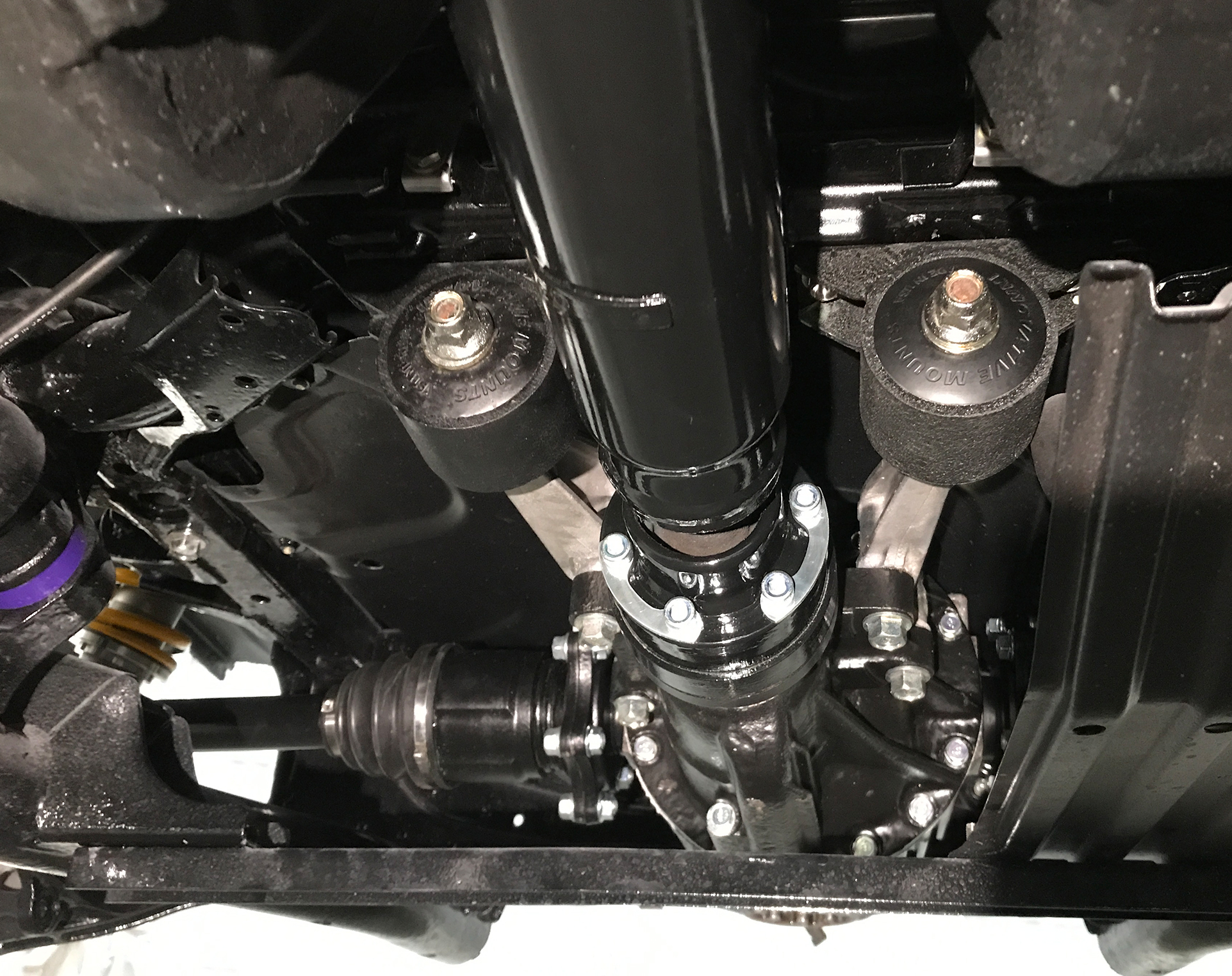
With the differential done, next up were the driveshafts.
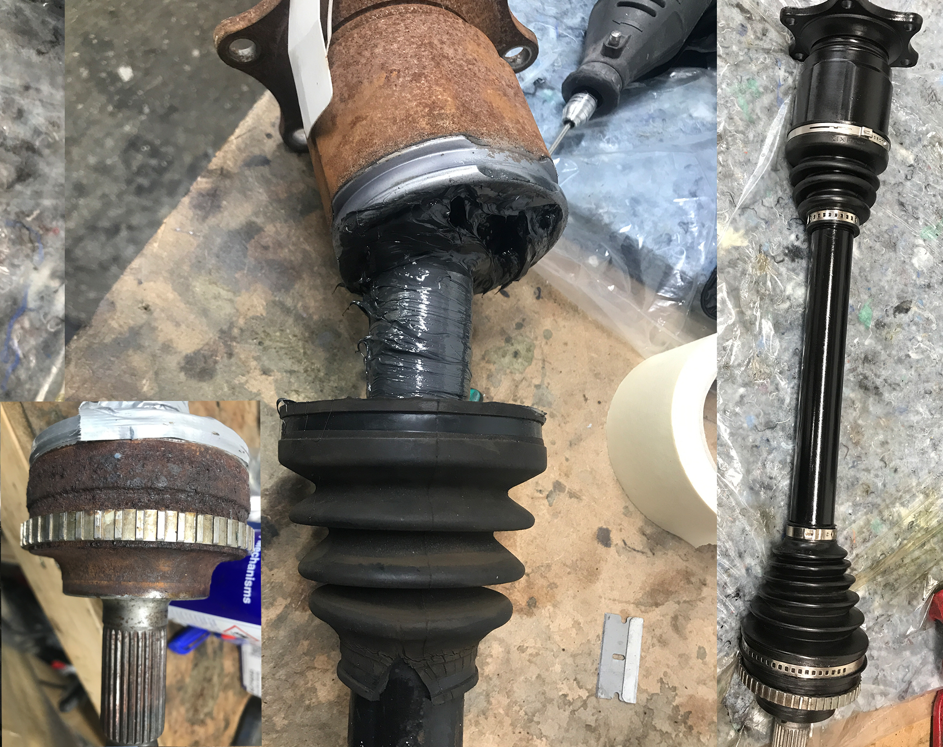
I had previously purchased a refurbished driveshaft from Ballade Sports, and while some of their products are great, others can be a bit hit or miss. Unfortunately, in my case, the driveshaft was a miss—at least based on my experience.
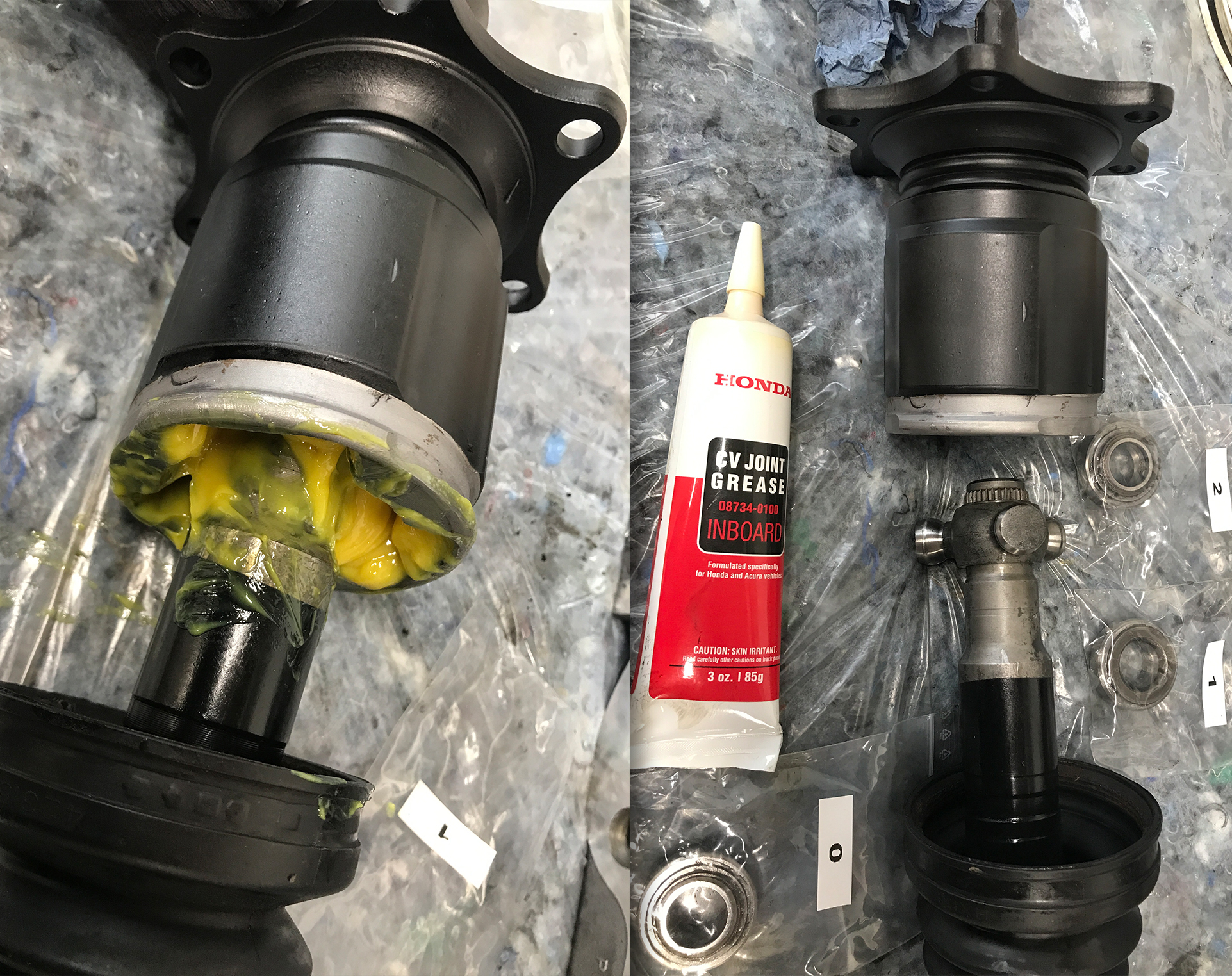
While it didn’t fail mechanically, after just 3–4 years, the cv boot developed numerous cracks and splits—something I hadn’t seen on other driveshafts I’d owned before, even much older ones. Additionally, the grease inside the inner cap wasn’t the original Honda grease. I’m no expert, but it looked more like the type used for the outer CV joint, which wasn’t ideal.
To fix this, I decided to replace both the inner and outer CV boots with new ones, along with the recommended Honda grease. I stripped them down, cleaned everything, and reassembled them. The process itself isn’t too difficult—the key part is keeping track of the bearings and their exact positioning in relation to the inner cap, ensuring they don’t get mixed up during reassembly.

Unexpected Setback with Wheel Bearings
A surprise awaited me when it was time to press the new wheel bearings into the knuckles and install the wheel hubs.
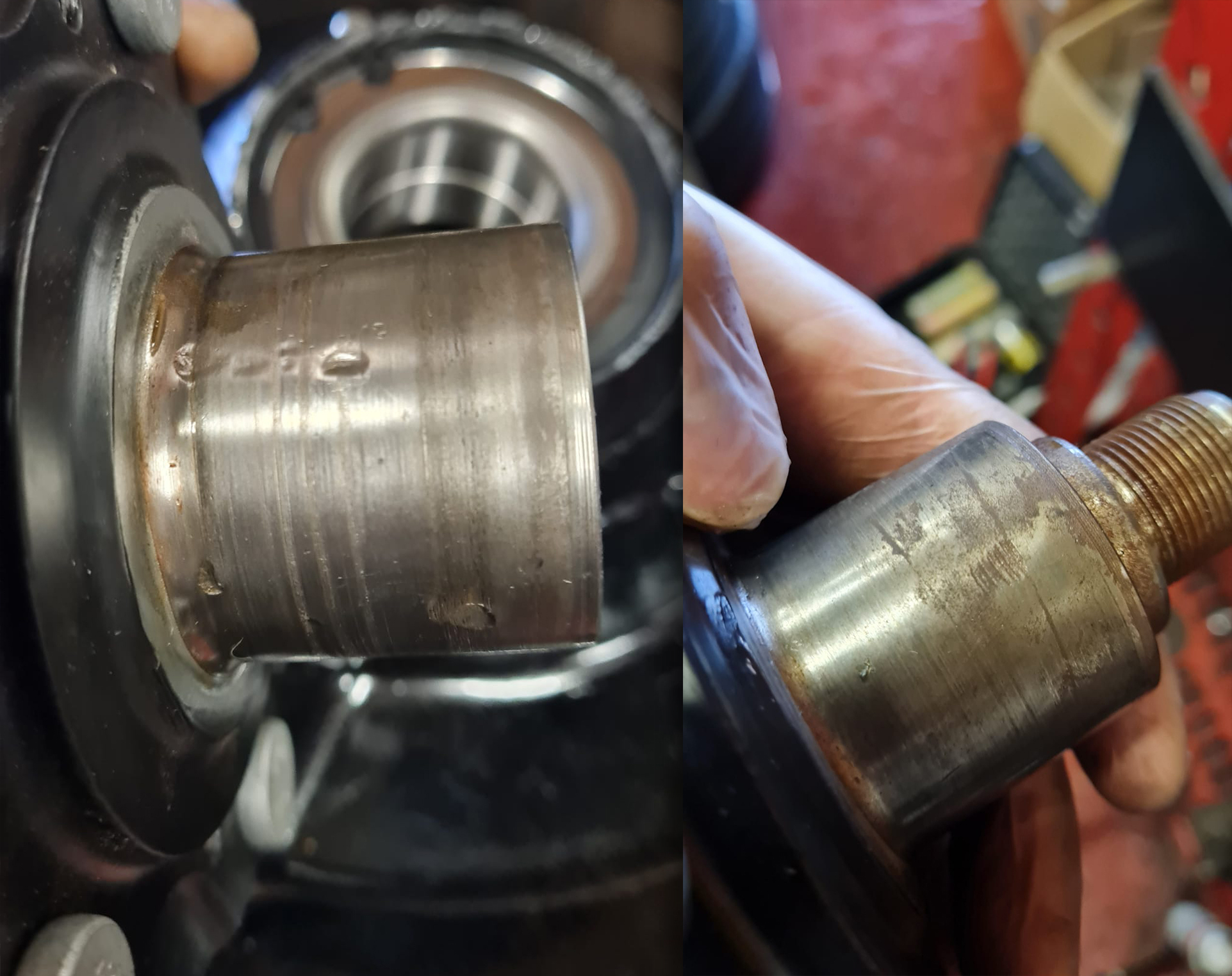
I should have inspected them earlier, but I failed to notice the damage—and it was no good. I had given the wheel knuckles to someone (I’m not going to name and shame) to press out the old bearings, as he had a press. He even offered to remove the remaining bearing part from the wheel hub. However, when I got them back, they were badly pitted, looking as if they had been hit with a hammer, and even had visible cuts on them.
When it came time for installation, the guy handling my differential rebuild sent me pictures showing just how bad they were. He advised me to get new ones, and he had no reason to lie—after all, I was sourcing them myself. Unfortunately, this led to an unexpected delay as I had to wait for new wheel knuckles to arrive from Japan.
Since I’m installing spacers, I also had to replace the wheel studs with slightly longer ones on the rear axle to properly fit the 15mm slip-on H&R spacers.
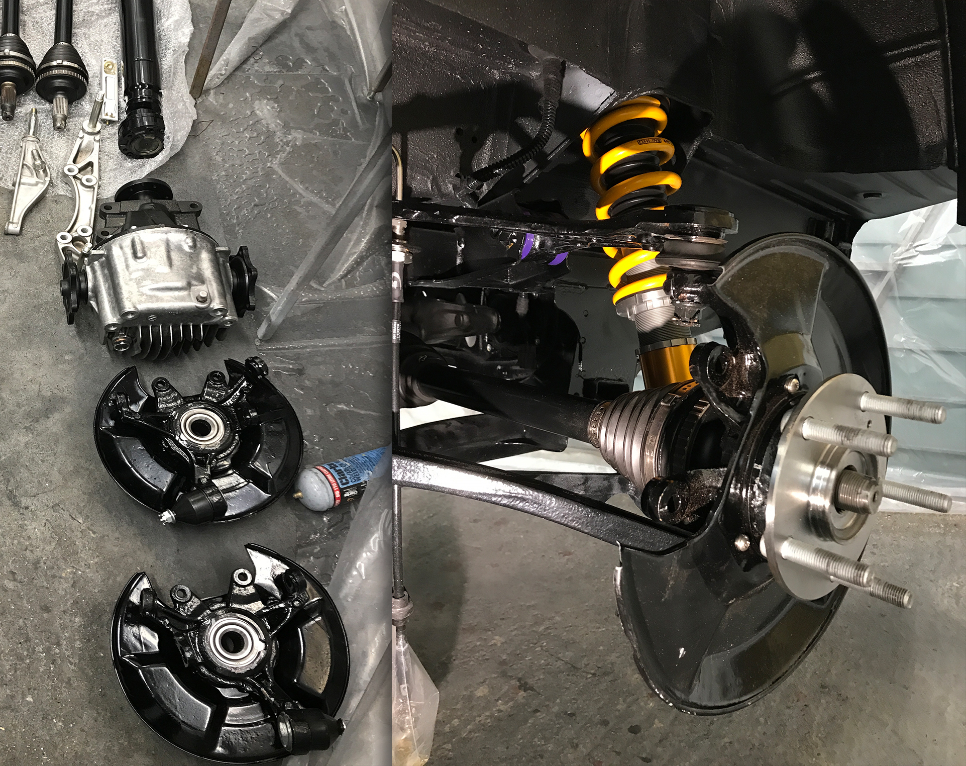
Another Task Complete
With this all sorted, it's time to move on. Next up: suspension and Big Brake Kit installation.

